IoT Journey With NodeMCU - Setup for development!
In Part 1 of this article we looked at preparation and IoT tool selection, getting all tools ready. In this post will set up our development environment and make NodeMCU alive with some code.
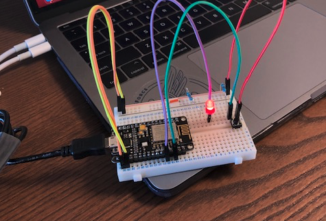
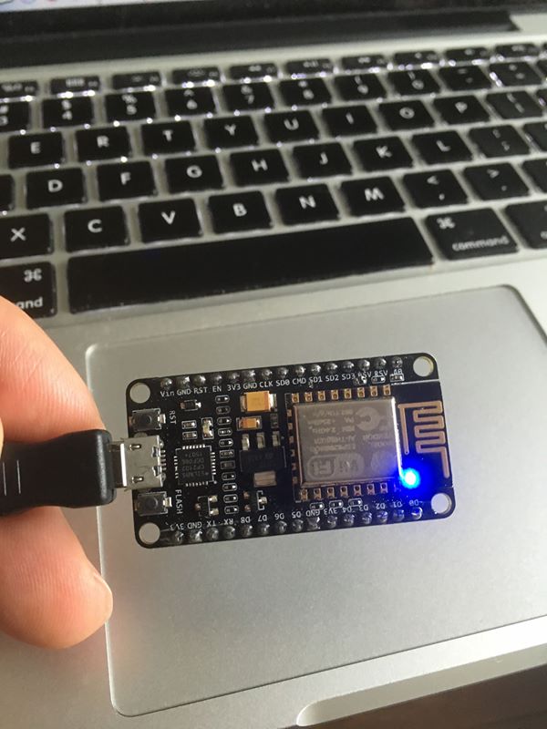
I will use ready NodeMCU unit with mini USB connector to link this to my MacOS (BigSur). But before that we need to do some configuration that. Note that some instructions may vary based on your device specs.
- Install and configure Arduino IDE
- Add Arduino ESP8266 extension to IDE
- Install USB drivers
- Test the unit communication with IDE
- Load some code to test
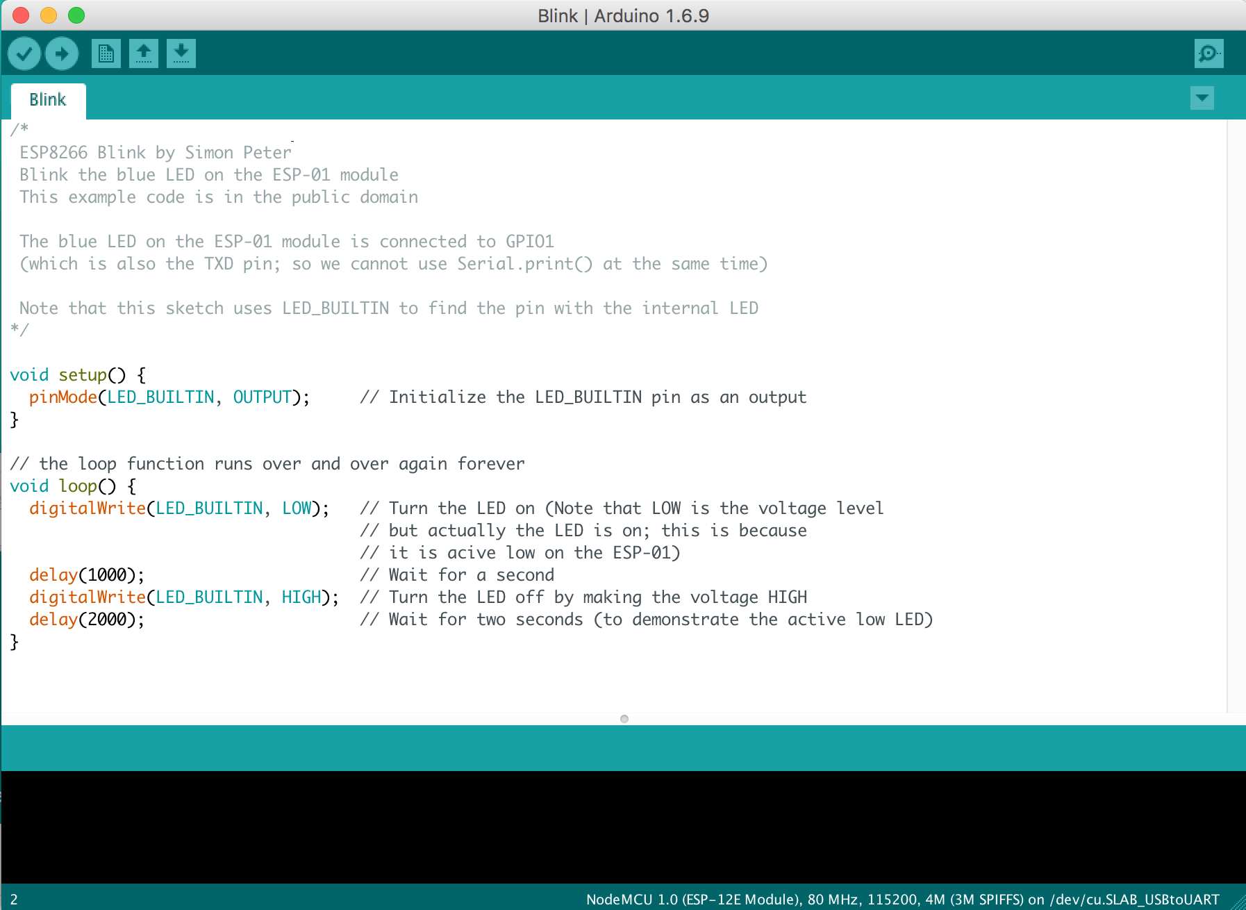
Install Arduino: 1.8.13 (Mac OS X) IDE download can be found here, download and install the version you need, I use MacOS BigSur version 11.2.3. Once you launch the IDE it will typically launch with sample loaded Sketch program for popular LED Blink code. A simple Sketch makes LED on/off blinking with some delay.
When I connected my NodeMCU unit to USB it has on board blue LED and it started blinking before I loaded anything. The maker of this unit Oddwires have preloaded that script on NodeMCU and that is ok. Good test to know device is working or not.
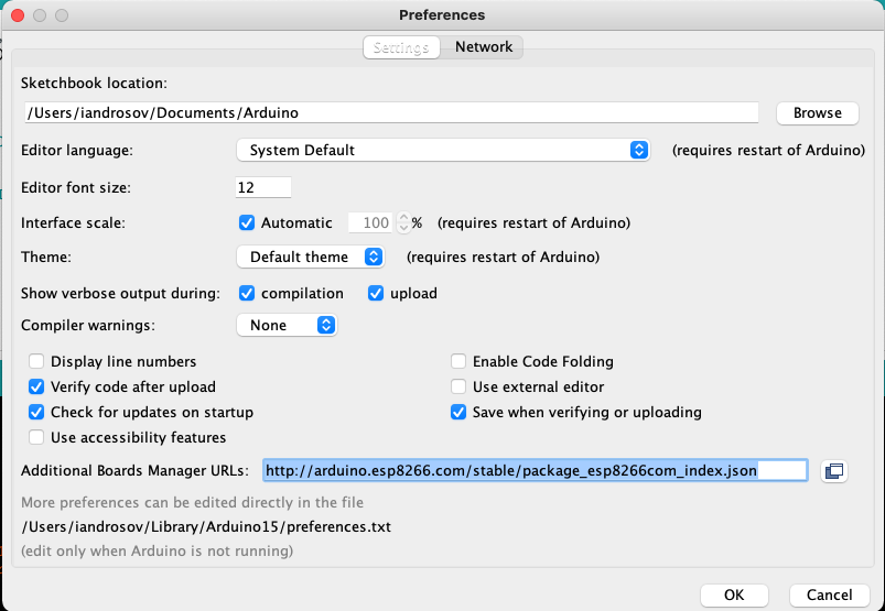
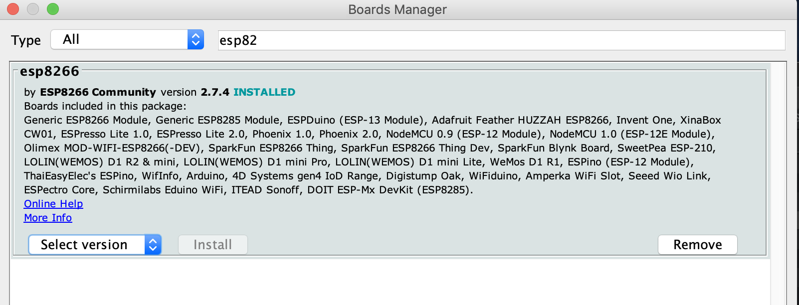
Next step we need to add Arduino ESP8266 extension to our IDE for development. Select IDE Arduino > Preferences from menu and enter http://arduino.esp8266.com/stable/package_esp8266com_index.json into the Additional Board Manager URLs field. This will add number of selections to IDE’s Tools->Board menu options
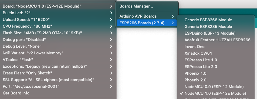
Open Boards Manager from Tools -> Board menu and install esp8266 platform and select NodeMCU 1.0(ESP-12E Module) from Tools > Board menu, after installation. This module corresponds to new NodeMCU development kit 2.0.
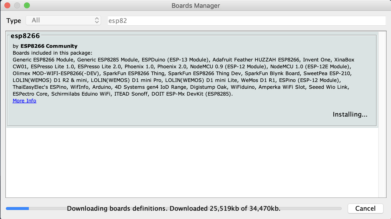
After installation is complete, we have a version 2.7.4
At this point we can start loading our code into NodeMCU device. For my MacOS this worked as expected and IDE is ready to connect.
Note on some systems we may need need to add USB communication to IDE to flash code to NodeMCU. In my initial [IoT post] I have mentioned that this dev-kit was built based on CP2102 USB UART chip. We need to install signed drivers for MacOS. from Silicon Labs CP210x USB to UART Bridge VCP Drivers. You will need to restart MAC OSX for this to take effect after install.
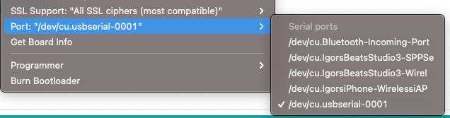
Connect NodeMCU unit with mini USB cable to MAC the LED will start blinking indicating normal power and working unit. In the IDE Tools -> Port menu select the Port for your device. In my case I made following selection depending on device:
- Port: /dev/cu.usbserial-00001
Select the Board type ESP8266 Board (2.7.4) -> NodeMCU 1.0 (ESP-12E Module) this is type of device I have, your kit may have some variation of this.
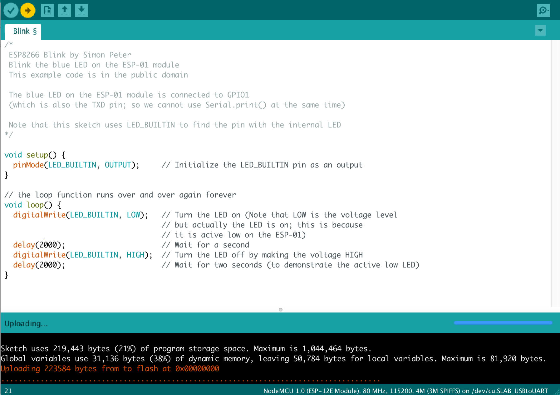
Note that Port will not show if device is not connected. Also if you do not see this or similar port selection this means that you do not have correct USB drivers. I had to tinker with this a little by reinstalling USB driver and restarting MAC and reconnecting unit. At this point these selections should be all good. Try to change delay(2000); compile Blink sketch.
Now lets try loading this sketch on our device.
After making a connection to my MCU USB that seem OK, attempted to load a sample sketch code to test my developer setup. This code below has nothing interesting other than blinking LED but good enough for testing.
void setup() {
  pinMode(LED_BUILTIN, OUTPUT);
}

void loop() {
  digitalWrite(LED_BUILTIN, LOW);

  delay(1000);
  digitalWrite(LED_BUILTIN, HIGH);
  delay(2000);
}
Code compiled successfully but, during program load step shows this error. Note this can occur on MacOS BigSur 11.2.3. If you run earlier MacOS or other Linux variants you may not see this error:
Arduino: 1.8.13 (Mac OS X), Board: "NodeMCU 1.0 (ESP-12E Module), 80 MHz, Flash, Legacy (new can return nullptr), All SSL ciphers (most compatible), 4MB (FS:2MB OTA:~1019KB), 2, v2 Lower Memory, Disabled, None, Only Sketch, 115200"

Executable segment sizes:
IROM   : 228624          - code in flash         (default or ICACHE_FLASH_ATTR)
IRAM   : 26752   / 32768 - code in IRAM          (ICACHE_RAM_ATTR, ISRs...)
DATA   : 1248  )         - initialized variables (global, static) in RAM/HEAP
RODATA : 688   ) / 81920 - constants             (global, static) in RAM/HEAP
BSS    : 24880 )         - zeroed variables      (global, static) in RAM/HEAP
Sketch uses 257312 bytes (24%) of program storage space. Maximum is 1044464 bytes.
Global variables use 26816 bytes (32%) of dynamic memory, leaving 55104 bytes for local variables. Maximum is 81920 bytes.
pyserial or esptool directories not found next to this upload.py tool.
An error occurred while uploading the sketch


This report would have more information with
"Show verbose output during compilation"
option enabled in File -> Preferences.
NOTE: When doing debugging with Arduino it is helpful to set yor IDE to Show verbose mode.
Google shows many such error examples. The solution is relatively simple, need to update one Python lib file list_ports_osx.py located on MacOS BigSur in this directory path.
~/Library/Arduino15/packages/esp8266/hardware/esp8266/2.7.4/tools/pyserial/serial/tools/list_ports_osx.py
- Open the file in your editor, my case I used Sublime Text with following commands
cd ~/Library/Arduino15/packages/esp8266/hardware/esp8266/2.7.4/tools/pyserial/serial/tools
open -a "Sublime Text" list_ports_osx.py
- Edit the code as follows, comment lines 29 and 30 and save. Add 2 code lines a shown bellow
#iokit = ctypes.cdll.LoadLibrary(ctypes.util.find_library('IOKit'))
#cf = ctypes.cdll.LoadLibrary(ctypes.util.find_library('CoreFoundation'))
iokit = ctypes.cdll.LoadLibrary('/System/Library/Frameworks/IOKit.framework/IOKit')
cf = ctypes.cdll.LoadLibrary('/System/Library/Frameworks/CoreFoundation.framework/CoreFoundation')
Big THANK YOU!!! for this detail to juanssl in this post for the tip that solved my upload error.
Upload sketch code and NodeMCU unit LED start blinking indicating successfull test.
After this code loaded, NodeMCU blue LED will start blinking with delay that we set in the code. While this is successful test we can agree that blinking LED is not very exciting.
Now lets try something more interesting like connect NodeMCU to WiFi and send remote commands to this device. We will make 2 endpoints to turn our LED On/Off with URL commands. We can use one of examples provided with ESP8266 extensions: Open File > Examples > ESP8266WebServer select HelloServer. This is a simple HTTP sever example code to setup our commands. Here is a full source code:
#include <ESP8266WiFi.h>
#include <WiFiClient.h>
#include <ESP8266WebServer.h>
#include <ESP8266mDNS.h>

const char* ssid = "...<WiFi SSID Here>..";
const char* password = "...<Password>";

ESP8266WebServer server(80);

const int led = 2;

void handleRoot() {
  digitalWrite(led, HIGH);
  server.send(200, "text/plain", "Hello from esp8266! NodeMCU Server");
  digitalWrite(led, LOW);
}

void ledOn() {
  digitalWrite(led, HIGH);
  server.send(200, "text/plain", "NodeMCU LED ON");
}

void ledOff() {
  digitalWrite(led, LOW);
  server.send(200, "text/plain", "NodeMCU LED OFF");
}

void handleNotFound(){
  digitalWrite(led, HIGH);
  String message = "File Not Found\n\n";
  message += "URI: ";
  message += server.uri();
  message += "\nMethod: ";
  message += (server.method() == HTTP_GET)?"GET":"POST";
  message += "\nArguments: ";
  message += server.args();
  message += "\n";
  for (uint8_t i=0; i<server.args(); i++){
    message += " " + server.argName(i) + ": " + server.arg(i) + "\n";
  }
  server.send(404, "text/plain", message);
  digitalWrite(led, LOW);
}

void setup(void){
  pinMode(led, OUTPUT);
  digitalWrite(led, LOW);
  Serial.begin(115200);
  WiFi.begin(ssid, password);
  Serial.println("");

  // Wait for connection
  while (WiFi.status() != WL_CONNECTED) {
    delay(500);
    Serial.print(".");
  }
  Serial.println("");
  Serial.print("Connected to ");
  Serial.println(ssid);
  Serial.print("IP address: ");
  Serial.println(WiFi.localIP());

  if (MDNS.begin("esp8266")) {
    Serial.println("MDNS responder started");
  }

  server.on("/", handleRoot);

  server.on("/inline", [](){
    server.send(200, "text/plain", "this works as well");
  });

  server.on("/on", ledOn);
  server.on("/off", ledOff);

  server.onNotFound(handleNotFound);

  server.begin();
  Serial.println("HTTP server started");
}

void loop(void){
  server.handleClient();
}
Note that on-board LED is controlled with simple commands
const int led = 2; // LED ID may be different depends on wiring
digitalWrite(led, LOW); // LED OFF
digitalWrite(led, HIGH); // LEAD ON
We have added 2 small methods mapped to URL path /on & /off to control LED switching.
void ledOn() {
  digitalWrite(led, LOW);
  server.send(200, "text/plain", "NodeMCU LED ON");
}

void ledOff() {
  digitalWrite(led, HIGH);
  server.send(200, "text/plain", "NodeMCU LED OFF");
}

 server.on("/on", ledOn);
 server.on("/off", ledOff);
Open serial monitor window Tools > Serial Monitor and upload this code to NodeMCU, you will see load progress. If you are doing this for the first time after this first load we need to restart NodeMCU device. Disconnect power or unplug NodeMCU device. After upload the server will start on the device. The Monitor window will print a welcome message along with IP address that we can use to send command to our IoT device.
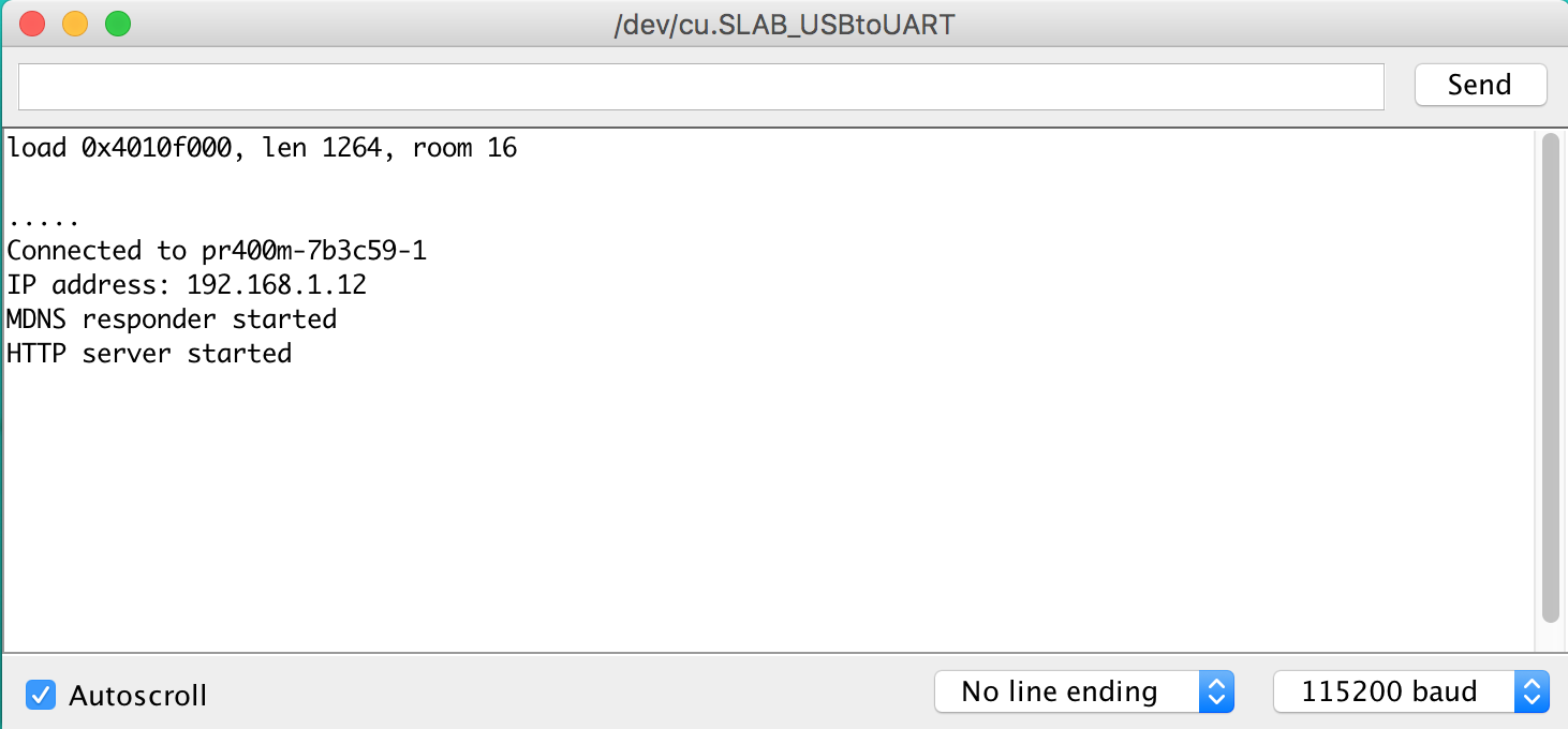
Open web browser and type this URL: http://192.168.1.12/on This acting will turn on LED light with blue light. Similar URL http://192.168.1.12/off will switch LED off.
Now lets sum our accomplishments, so far we have completed:
- Set up our development system with Arduino IDE for NodeMCU
- Connected our IoT device and tested it
- Made connection to our WiFi network
- Started to control NodeMCU from browser
Very good starting point for our next IoT development project. That will be a new Trailblazing!